Audio SiP and System
Audio SiP and System
Introduction
The solution is designed for low cost, high quality, low latency (<20ms) and environment friendly audio applications using 2.4 GHz and 5.8Ghz. The core circuit is a RF SiP, which includes PA, SW, Transceiver, MCU and EEPROM with dimension 9x13mm or 8 x12 mm.
The output power will be 18 dBm/120mA current@3V using TM1001 and 10 dBm/60mA@2V using TM1008. The SiP can connect to Major Mobile phone, notebook and Table let.
The system( not in Sip) must have a codec >24 bits and 48K/96K/192K sampling rate to transfer the analog signal to digital signal and compress( compression algorithm?) it for lower data rate to transmit it. The compressor can be hardware or software. The system can be in a group, which has a master and 4 clients. It means 1 transmitter and 4 receivers without paring needed.
For getting friendly spectrum environment, we use 16 dBm Pout (lower power consumption) to connect master and clients, but hopping <300 times/sec to keep good low and high frequency response.
We can use 2.4Ghz 4Mbps Transceiver for the 1st version in “direct mode” to get better band width efficiency. But we need to define our own data format. Data Frame format planning is needed.
The speakers (Low, Mid and High) are derived by Class D amplifier. Before the class D amplifier must have a shaping circuit to reduce the high frequency port.
The system features:
For the audio system, it should have a SiP, Codec, Class D-amplifier, speaker, Microphone, LC shaping circuit,
The features are:
- 1*Tx to 4* Rx ( max) in a group
- Every Receiver can register 10 Txs and can be polled while pushing a button.
- No pairing needed, but push 〝Paring〞button and then registered (max 1 to 4)
- Transmitting music thru the wireless Dongle( D-type, Android, 32 pin, lighting, USB) to Speakers
- Microphone signal can be combined into Music as Karaoke.
- Dong can be a Music-Bank (music sources) thru wireless connecting to Mobile phone or Notebook.
- Low current power consumption, but Distance >50 Meters in pocket
- Delay line design for timing adjusting
- Audio SiP cost <USD$1.8 with 4 Mbps data rate at 2.4Ghz and 6Mbps data rate at 5.8Ghz
- LED indication: in-group( registering), pairing, working, power on, low power
- Codec: Sampling rate 24 bit and 48K and 48bits and 192K
Strategies
- A Sip has same circuit (same MCU) and pin assignments as Ginseng SiP, but different dimension and marking, but fully match EE’s firmware.
- Using a new MCU to design a different low cost Audio SiP with different dimension. We may have a +1.8V version (same as Saffron), which has +1.8V Bias voltage or lower current consumption. We need to have a +3.3V as well. It has PA, LNA, Transceiver EEPROM and MCU (same as Octavia).
Data Treatment
Typically audio is samples with 24-bit ADCs, with the data path into the Cortex MCU wireless processor being 16 bits x 48 k samples/sec per full-range channel. Once inside Cortex MCU, the audio is processed with a high-speed data compressor, reducing the audio payload from 768 kbps to 240 kbps per full range channel. Note this is a data-reduction step, not to be confused with dynamics compression which is not done by TM at all. It is important to note that this data reduction step is critically important as it enables the narrow-band RF strategy detailed above. The compression is done using an optimized ADPCM-class algorithm developed at TM called HPX™. HPX™ has a THD+N of less than 0.01% across the 20Hz – 20kHz audible range. The HPX codec is employed in all of TM’s full range (20Hz-20kHz) wireless audio solutions including the TM2110 and SKAA® operating systems. The use of HPX to reduce data payloads is key to TM’s high QoS & coexistence strategy—HPX effectively allows the RF footprint to remain very slim and TM’s solutions therefore boast an industry best combination of QoS and coexistence with other devices sharing the band. Note 0.1 audio subwoofer channels are sampled at 6 kHz and are not compressed with HPX (LFE data is sent uncompressed in the TM2110 operating system). The raw data rate of the RF physical devices used in TM’s hardware is 2.0 Mbps. In a 2-channel audio solution such as SKAA, 480 kbps of payload is sent over a 2.0 Mbps physical link. The difference between the physical device data rate and the payload data rate is called the data rate margin (2,000 – 480 = 1,520 kbps). This margin is used to accomplish packet framing, checksums, feedback, control channels as well as transmission of redundant data. The fact that TM’s protocols are designed with a “healthy” data rate margin is one of the key contributors to TM’s well-known robustness. At the receiver, the data, having been received, quality controlled, error corrected and buffered by Cortex MCU is then decompressed and output at 16 bits x 48ksamples/sec per full-range audio channel. So in summary, audio compression is used to achieve a reduced data payload, the reduced data payload enables a narrow-band hopping approach (with simple FSK modem), and the narrow-band hopping approach enables an industry best combination of QoS and coexistence.
Protocol
TM has created a particularly strong method of adaptive frequency hopping, for which TM has an issued patent. Frequency hopping sends information on multiple frequencies and works as follows. The Cortex MCU processor keeps track of several A channels and several B channels in the RF domain. Channels are the foundation channels (they are known good—the clearest, best performing channels in the band) and so primary information is always sent on them. B channels are experimental channels so redundant information is sent on them—sometimes data gets through and sometimes it doesn’t. The palette of B channels is continually changed, moved from frequency to frequency. Performance stats are kept on all A channels and all B channels. When a B channel is found with better performance stats than the worst of the A’s over a period of time, that B channel is upgraded to A channel status and the worst of the A channels is dropped from the A palette down to the B palette. The WFD protocol has proven its capability in delivering flawless audio even in heavy interference environments such as technology trade show floors. Frequency Hopping is the communication protocol used in all of TM’s operating systems including SKAA and TM2110.
Duplex
TM never simply broadcasts audio data from point a to point b. Although the audio is traveling only in one direction, the RF communication is always bidirectional. The transmit node always maintains a 2-way (duplex) communication with the receive node. This means each receive node can return critical feedback to the transmit node such as if any audio packets arrived damaged (and therefore need to be resent) as well as statistics on RF channel performance. With TM duplex communication is a rule—even in multi-node solutions where there is more than one receive node. The communication between the transmit node and each receive node is always “closed loop”. TM’s operating systems support multiple receivers (in SKAA for example, up to 4)— all of them still maintaining closed-loop communication with the transmit node. Latency and Receiver Sync. For an audio delivery system, latency typically matters a lot (for example in Home Theater applications). TM provides fixed latencies which are very stable. In fact sync between 2 receivers in the same system is maintained within 40 micro seconds nominally (output time difference between Rx units in the same system). The absolute latency can be set by adjusting the audio data buffer size. For same-room home theater applications, latencies (Tx to Rx end-to-end) as low as 10 ms are available (easily meeting Dolby’s rule of max 20 ms for home theatre rear speakers). For multi-room audio, latencies may be greater and TM offers up to 40 ms (and the associated QoS boost associated with larger buffers). The key in any true real-time audio system is that latencies are fixed, predictable and exactly repeatable each time the system is powered up.
System block Diagram
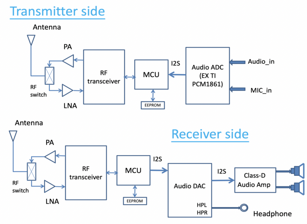
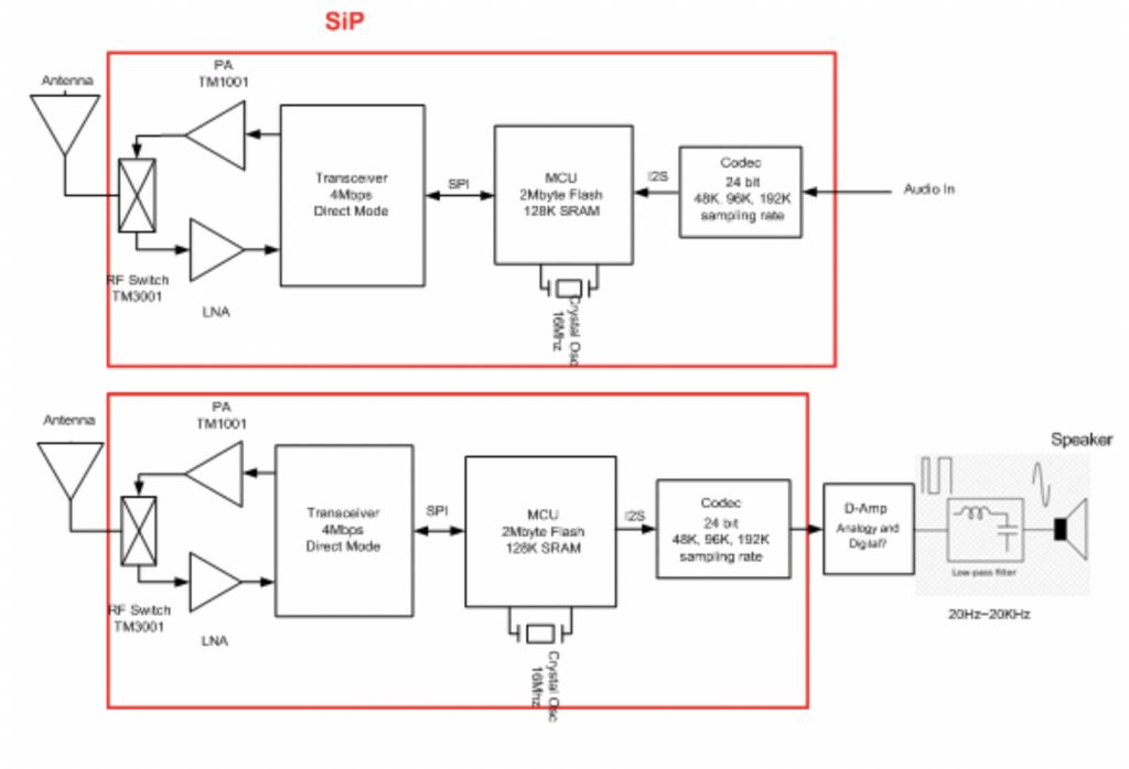
The Audio block system is for IOT applications. We like to find audio signal compression software, which can reduce the signal down to 30%. The MCU is a Cortex M4 with 2048K flash and 128K SRAM. And please suggest the codec being in SiP or not.
SiP Block diagram:
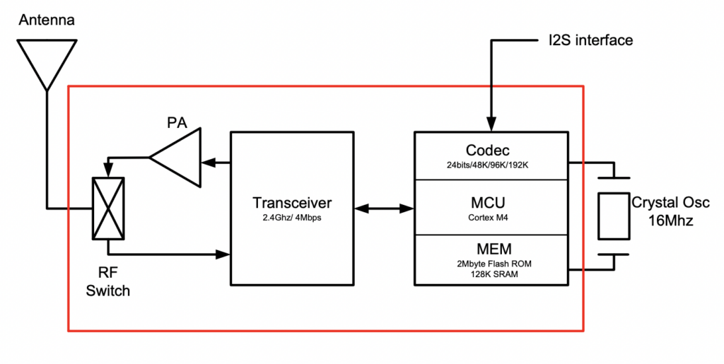
MCU performance and capability:
- Cortex M4 -70 MIPs/100MHz
- 32 bits
- I2Sx1 /SPIx2 /UARTx1/IOx8/I2Cx1
- Flash 32K, DRAM 32K
- 4 PWM
- 16Mhz clock reference
Software: Applications and Libraries
Applications:
- Speaker 2.1, 5.1
- Sound bar
- Head phone/ear phone
- USB Dongle as a music bank, receiving signal from Mobile phone.
- Karaoke/Microphone
- Karaoke x 2 and combine to music
Some new idea
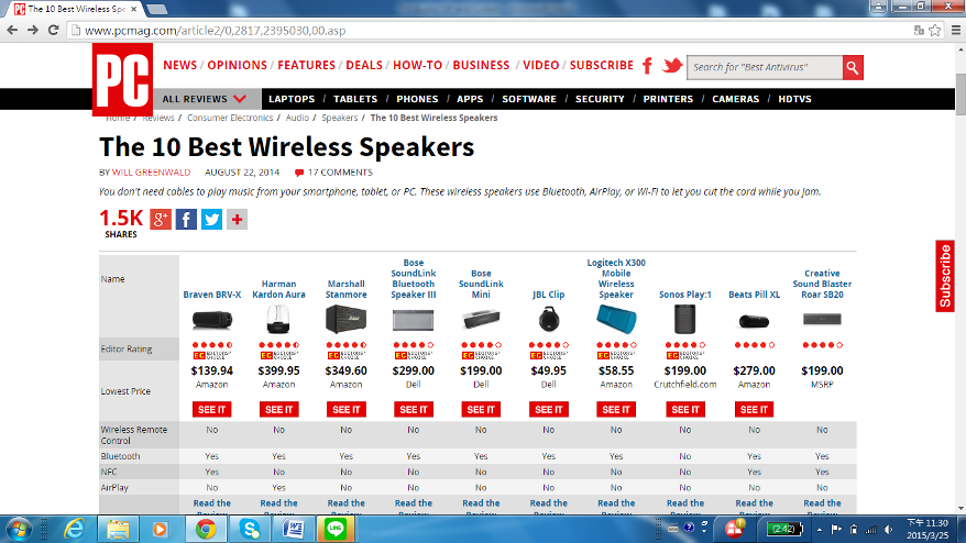
After checking the 10 best wireless Speakers, we found out Bluetooth has swept the market already. We need to study Bluetooth performance using Audio applications.
Idea is that we may combine SiP and Bluetooth sonly on substrate for Audio applications.
Scenario 1
One Tx to Multiple Rxs (up to Max 6 pcs)
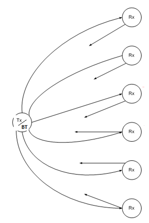
- Voltage supply: +3V
- Start from one to one
- When is good timing, that TX will ask Rx to do hopping? Condition?
- Target: 24 bit Codec/48K sampling rate, same as EE , we hope: 24Bit/96K sample rate.
- Structure: TM1001+TM3001+ $Mbps Transceiver+ Cortex M4 MCU+ D-Amplifiers+ LC shaping circuit+ Speakers

